Real-Time Hardware-Determined Feature Edges
Abstract
I implemented Morgan McGuire and John F.Hughes's Hardware-Determined Feature Edges paper, and introduce the notion of a "partial silhouette".
Edge detection is performed entirely in vertex shaders.


A preprocessing step computes the edges of the model. For each edge, four nearly identical vertices are set down the graphics pipeline. Each of those four vertices contains a bundle of adjacency information about that edge. The vertex shader uses that information to determine if the edge should be drawn, and if so extrudes the four vertices to a screen-aligned quad. This quad can then be textured and colored in various different ways.
The information passed to the vertex shader includes position and normal of the vertices defining the edge, as well as the position of the vertices of the adjacent faces. Face normals of the adjacent faces can be recomputed from those positions.
To determine if an edge should be drawn we can use the following expressions:

Contour: [ nA • (eye - v0) < 0 ] XOR [ nB • (eye - v0) < 0 ]
Ridge: [ nA • nB < cos θR ] AND [ ( v3 - v2 ) • nA ≤ 0 ]
Valley: [ nA • nB < cos θV ] AND [ ( v3 - v2 ) • nA > 0 ]
Marked or Boundary: v3 = v0
Partial Silhouette Detection

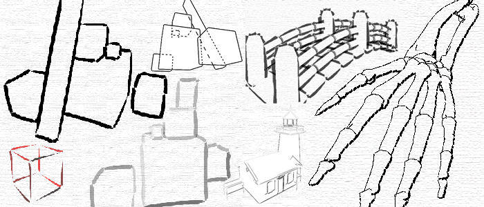
This image shows a rendering using partial contour detection. Using the default algorithm, as the scene changes, different contour edges are identified, creating an unpleasant "popping" effect. To remedy this, I transform the discrete version of the XOR into a continuous version.
One way to implement continuous logic functions (ie. with values between zero and one) is using fuzzy logic:
¬a = 1 - a
a AND b = min(a, b)
a OR b = max(a, b)
a XOR b = ( a AND ¬b ) OR ( b AND ¬a )
I pass the two dot products nA • (eye - v0) and nB • (eye - v0) (scaled to the [0,1] range) as argument to this continuous XOR to determine how much a certain edge is a contour. I then set the alpha value of the edge to that value.
However this version of XOR does not produce satisfying results for typical edge data: edges are being displayed in half opacity on average. A stronger version of XOR that can eliminate more edges is needed.

I use the following definitions to implement this stronger XOR:
a XORs b = ( [ max( a XOR b, .5) ] - .5 ) × 2
In terms of fuzzy logic, this is the output membership function, where the input is the value of XOR, and the output is the alpha value of the edge (between zero and one). It is shown in the figure to the right.
For comparison, the values of both functions for a sample range of arguments are:
| XOR | 0 | .25 | .5 | .75 | 1 |
| 0 | 0 | .25 | .5 | .75 | 1 |
| .25 | .25 | .25 | .5 | .75 | .75 |
| .5 | .5 | .5 | .5 | .5 | .5 |
| .75 | .75 | .75 | .5 | .25 | .25 |
| 1 | 1 | .75 | .5 | .25 | 0 |
| XORs | 0 | .25 | .5 | .75 | 1 |
| 0 | 0 | 0 | 0 | .5 | 1 |
| .25 | 0 | 0 | 0 | .5 | .5 |
| .5 | 0 | 0 | 0 | 0 | 0 |
| .75 | .5 | .5 | 0 | 0 | 0 |
| 1 | 1 | .5 | 0 | 0 | 0 |
Here is a comparison of the two methods as animated gifs:


A further improvement can be achieved by noting that our refined method clamped the result values at .5 which corresponds to an edge being viewed straight on (the dot product between the eye vector and one of the face normal is zero). However in this case, the edge should still be visible, but only slightly, as it is about to be culled out. The solution is to simply lower the threshold by a small amount, to a value of about .45.

a XORt b = ( ([ max( a XOR b, t) ] - t) / ( 1 - t) )
with t = 0.45
This more correct version of the output membership function is shown in the figure to the right.
Increasing the threshold culls more edges. The next figure shows a comparison between t=.5 (left), and t=.45 (right)


This is particularly noticeable on a realistic model:


The same comparison as before, encoded in XVid format:


Partial Silhouette Detection (4.7mb)
This video also shows fist shows the effects
or reducing t to 0 then back up to about .42
Texture Coordinates Computation
Two different ways of determining the texture coordinates of each quad are defined. The simplest one always sets the same coordinates by applying the entire texture to each quad. The other uses the center of the object to determine the direction of the stroke, and then uses screen coordinates to parameterize it. This produces better results with highly tessellated models.
Other Features
To display hidden contours, we first render the edges and model as usual, then invert the culling function of the z-buffer, and render the edges again with a dotted line.
A collection of key frame textures can be specified to animate the strokes over time. This can be used to duplicate the artistic style of hastily redrawing every keyframe without bothering about coherence.
Download the preliminary Feature Edges Demo (with Cg source code). Note that at the time I had trouble stuffing all the data into a VBO, so the slowdown on large model comes from the fact that the vertex data is sent from the cpu every frame.


This shader changes the width of each edge based on how "lit" it is. The black sphere is the point light source.


